The Step Controller module works with a LT110 Ride Height Sensor to create four outputs to drive step retards on an ignition controller. Each output switches to 12V when the output is enabled, and is pulled to ground when off. The status of the four outputs is shown with individual LED indicators.
Each time the Step Controller is powered up, the ride height from the LT110 is measured. This is considered the baseline ride height. At set increases in the ride height from this baseline, the Step Controller will incrementally enable the outputs 1 through 4 in sequence. The increase in ride height that is needed for the ride height to increase by before an output is enabled can be programmed with switches accessible from the Step Controller front panel.
By default the Step Controller is paired with a 0-40″ range LT110 Ride Height Sensor. With this combination there are two configurations available, depending on how much total travel required:
- Standard Range – Default ride height step increments of 0.75″, with range from 0.75-2.5″. Total range for all four outputs to enable is therefore 3-10″ of total range.
- Extended Range – Default ride height step increments of 1.5″, with range of 1.5-5″. Total range for all outputs is therefore 6-20″.
Download Step Controller Datasheet
Notes:
- The LT110 sensor is powered through the Step Controller. Use the LT110 sensor cable to provide
power and signals from the LT110 to the Step Controller. - Outputs are enabled without disabling any previous output. For example, when Output 2 is
enabled, Output 1 is still enabled ( see video in gallery which shows operation). - The programming switches are numbered 1-4 from left to right. Moving the switch up turns the
switch on. - For the Standard Range version, with Switches 1-3 off, the default ride height step increment is 0.75”. Switches 1-3 can be used in
combination to get any ride height step increment from 0.75-2.5” in 0.25” increments. - For the Extended Range version, with Switches 1-3 off, the default ride height step increment is 1.5”. Switches 1-3 can be used in
combination to get any ride height step increment from 1.5-2.5” in 0.5” increments. - LED’s indicating the status of Outputs 1-4 are numbered left to right.
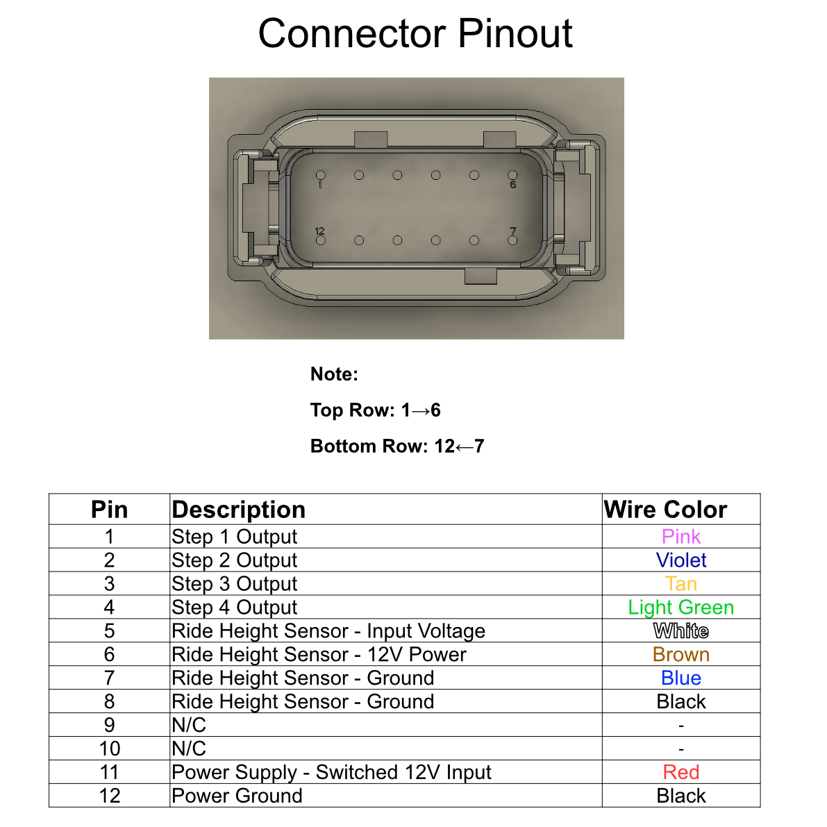
- Mating connector is a Deutsch DTM 12 pin, with pinout below.